Absorption imaging of thin liquid flims
Liquid films play an important role in many practical processes (e.g., tribology, thermal management, energy conversion, water desalination, and fire suppression), whether they support them or can unintentionally interfere with them. Therefore, a detailed characterization of the temporal development of aqueous films is desirable to optimize and further develop these processes. This requires preferably non-invasive measurement techniques to characterize the aqueous films with respect to film thickness, solute concentration, spatial extent, and the temporal evolution of these quantities.
Light absorption is well suited for this purpose if the liquid film exhibits characteristic absorption lines in the spectral region of investigation. For aqueous films the water absorption bands in the (near-)infrared spectral range are well suited for absorption measurements. In combination with diode lasers as light source, this method is extensively used in gas-phase analysis, where gas mixtures are analyzed point by point with respect to concentrations and temperatures. Using the water absorption band at ~1.4 µm, this method has been successfully used for the pointwise characterization of aqueous films in the 100–1000 µm film thickness range, simultaneously determining the concentration of a solute or the temperature of the film. The extension of the usable spectral range to longer wavelengths enabled the use of stronger absorption bands (at 1.9 or 3 µm) and thus the possibility to measure lower film thicknesses. Likewise, the layer thickness and concentration of two dissolved urea derivatives of an aqueous solution can be measured simultaneously. The use of near-infrared cameras with spatially and temporally resolved detection enables dynamic film thickness imaging measurements of thin water films.
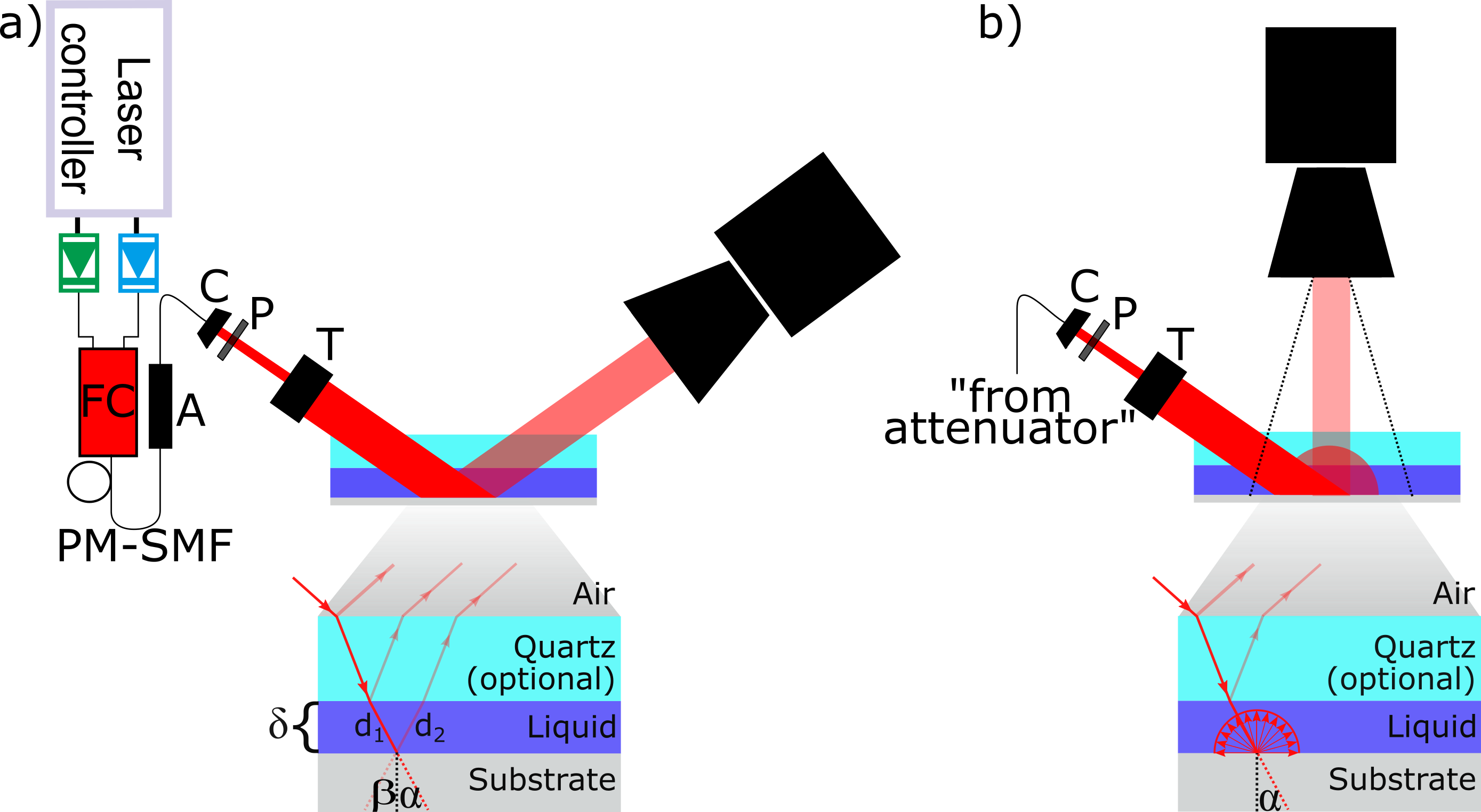
Optical setup for a time-division multiplexed (TDM) thin-film absorption imaging sensor in reflection mode utilizing the specular reflected light from a polished substrate (a), or the diffusely back-scattered light from a matte-finish surface (b). Both cases only differ in the arrangement of the detector. FC: Fiber combiner, PM-SMF: Polarization maintaining single-mode fiber, A: Attenuator, C: Collimator, P: Polarizer, T: Telescope optics. An enlarged view of rays entering and exiting the probe volume is given below each setup. The quartz window is optional and used here to generate variable film thicknesses for calibration measurements.
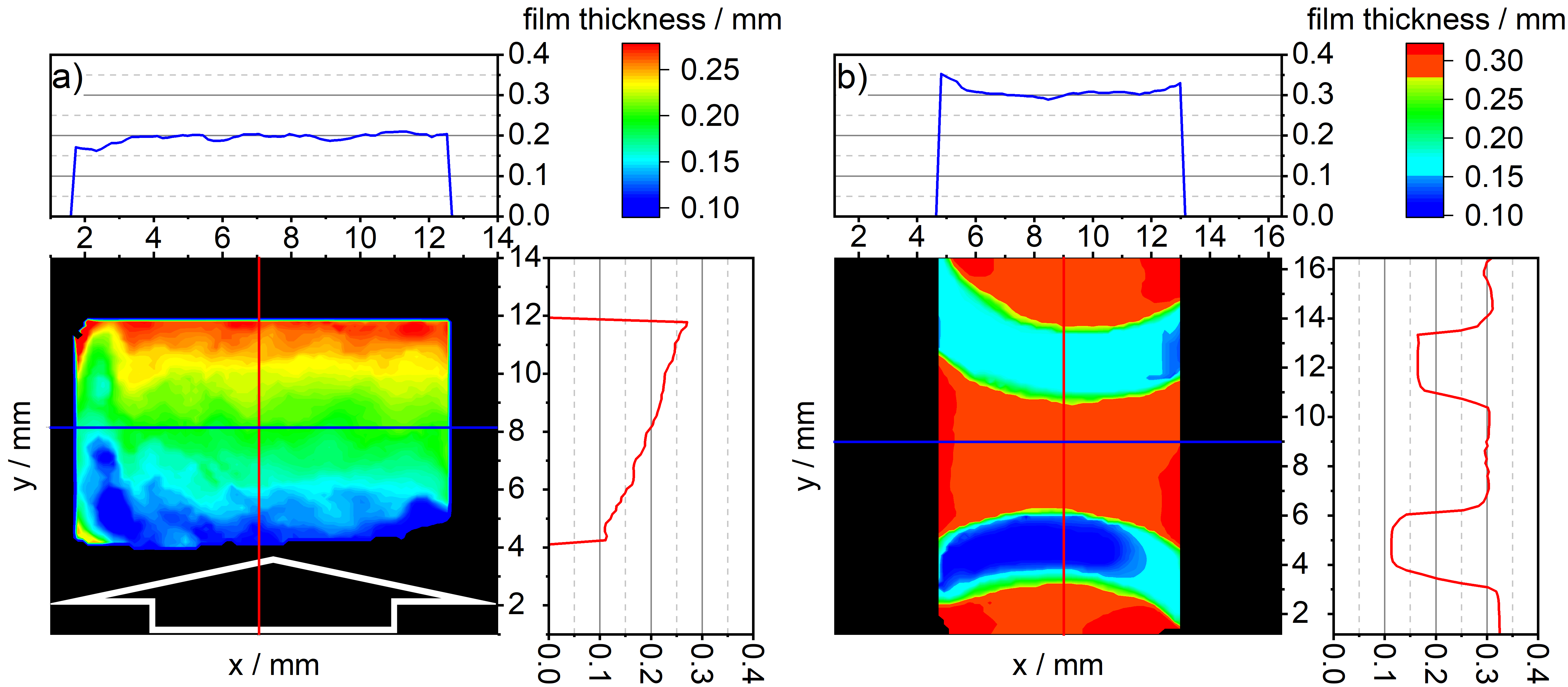
2D film-thickness images (color-coded thickness values) and profile plots along two orthogonal axes across the image (red and blue lines). Image areas not processed are colored in black. (a) Specular reflection mode (Fig. 1a) for a polished aluminum support surface; (b) orthogonal reflection mode (Fig. 1b) for a diffuse or matte-finish aluminum support surface. The white arrow in the left figure indicates the direction of incidence of the laser beams onto the targets.
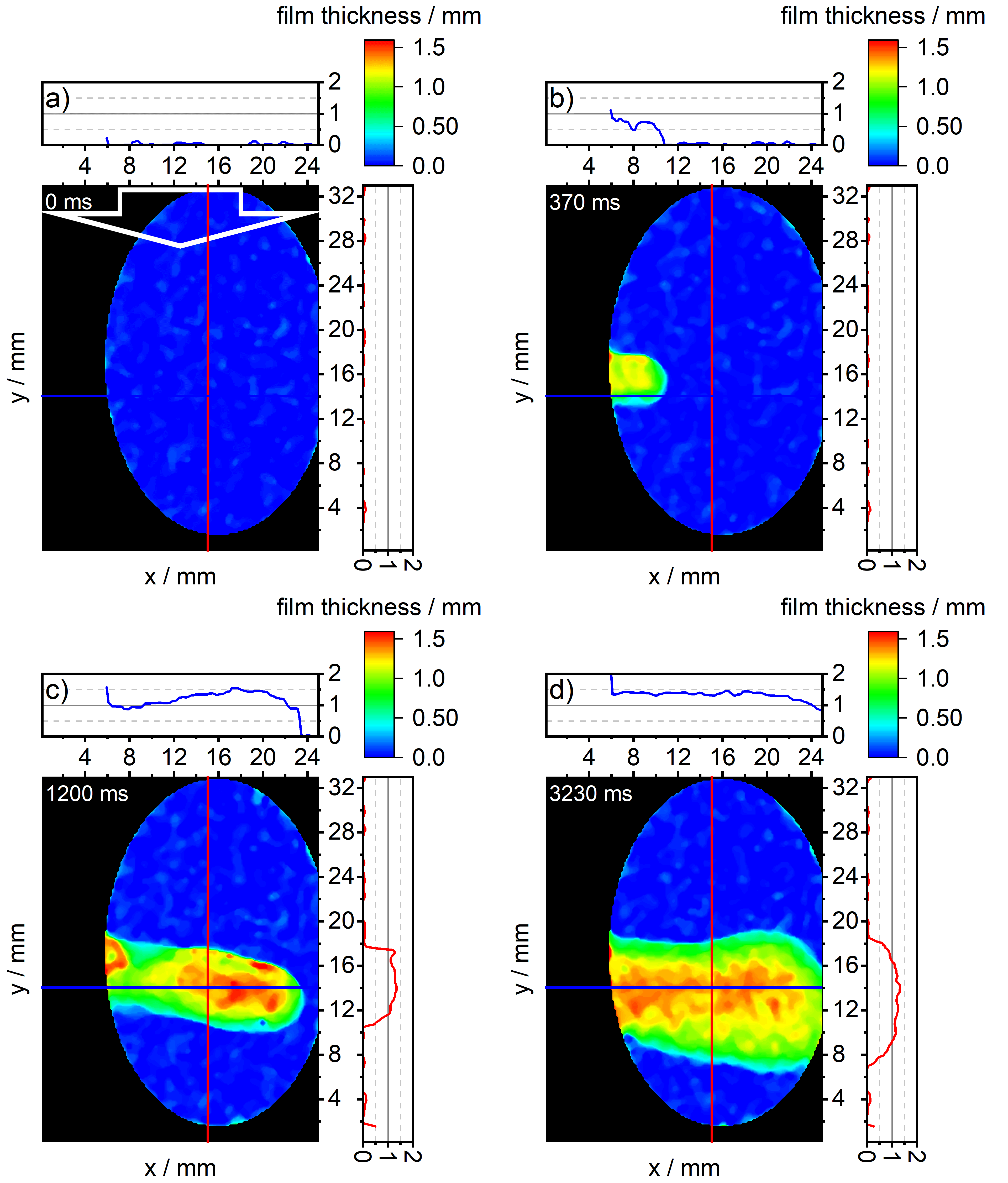
Frames with 1 ms camera integration time from a 100 Hz movie showing a 50 % water/ethanol (by mass) mixture injected by a syringe (out of the image to the left) onto an inclined (gravity assisted flow from left to right) matte-finish substrate. (a) nearly dry substrate before liquid impingement, (b)−(d) liquid flow 370, 1200, and 3230 ms after impingement, respectively. The white arrow in the upper left figure indicates the direction of incidence of the laser beams onto the targets.
For fuel films, such as a surrogate fuel consists of iso-octane and highly concentrated toluene, the film thickness could also be determined by absorption measurements. Toluene is a widely used fluorescence tracer that helps researchers visualize the evaporation and combustion processes of fuel films. Direct injection engine could produce some fuel films down to the order of micrometers, while the combustion environment poses additional challenges because of interfering absorption caused by other species present during heat-up and combustion.
A multispectral UV-VIS absorption technique has been developed to detect the fuel film evaporation even under combustion conditions, utilizing a high-speed 2D imaging system. While the absorption information from the liquid-phase fuel film is captured using a 265 nm UV-centered LED, other interferences—such as absorption by toluene vapor, scattering by the liquid, extinction by soot and soot precursors, and soot incandescence—can negatively affect the real absorbance. To address these interferences, additional LEDs and morphological image processing are employed. This multi-spectral approach enables spatio-temporally resolved measurements of fuel film thickness.
The absorption concepts are extendable by different light sources, such as diode lasers or spectrally filtered broadband light sources, as well as detectors, such as photodiodes or imaging pixel cameras. So far, absorption spectroscopy has demonstrated good adaptability in the field of liquid film measurement.
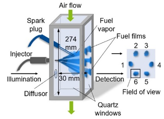
a) Thin fuel films are generated by the optically accessible atmospheric-pressure
constant-flow facility with injector and spark electrodes.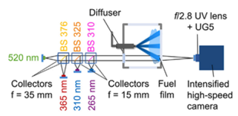
b) Optical layout around test section of flow facility.